LS Wiring Harness Instructions: An Overview
LS swaps are incredibly popular, driven by the Chevrolet LS engine’s reliability and performance. Successfully completing an LS engine swap hinges on a correctly wired harness, demanding careful planning and execution. Understanding the harness’s core components—wires, connectors, and the ECU—is vital for a smooth installation.

Understanding the LS Swap Popularity
LS engine swaps have exploded in popularity within the hot rod and performance automotive communities, and for good reason. The Chevrolet LS series small-block motor offers an exceptional power-to-weight ratio, robust reliability, and readily available aftermarket support. This makes it a compelling choice for upgrading a wide range of vehicles. However, the swap isn’t simply bolting in an engine; a crucial element is the wiring harness.
The LS engine’s modern electronic control systems require a properly integrated wiring solution. Many enthusiasts initially underestimate the complexity of this task, leading to frustration. A well-planned harness installation ensures optimal engine performance, driveability, and crucially, avoids potential electrical issues. The availability of both universal and vehicle-specific harnesses further fuels the LS swap trend, making it accessible to a broader range of skill levels and budgets.
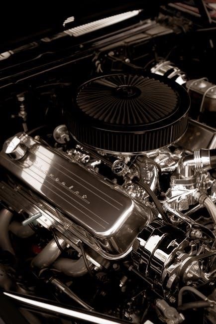
The Core Components of an LS Wiring Harness
An LS wiring harness isn’t just a bundle of wires; it’s a sophisticated network connecting the engine’s sensors and actuators to the engine control unit (ECU). Key components include the main harness body, containing power and ground wires, and dedicated connectors for sensors like the MAP, TPS, and coolant temperature sensor. Fuel system wiring, for the fuel pump and injectors, is also critical.
The ignition system wiring, handling coil packs or distributorless ignition, forms another vital part. High-quality connectors are essential for reliable connections, resisting corrosion and ensuring signal integrity. Many harnesses include provisions for accessories like air conditioning and electric fans. Understanding each component’s function and proper connection is paramount for a successful and trouble-free LS swap;
Planning Your LS Wiring Harness Installation
Careful planning is crucial before starting. Determine your engine management system, choose between universal or specific harnesses, and gather all necessary tools and materials beforehand.
Determining Your Engine Management System
Selecting the right engine management system (EMS) is foundational for a successful LS swap. Options range from factory ECUs, requiring reprogramming, to aftermarket systems like Holley or FiTech. Factory ECUs are cost-effective if retaining stock functionality, but may need professional tuning for modified engines. Aftermarket systems offer greater flexibility and control, particularly for high-performance builds or significant engine modifications.
Consider your project’s goals. A mild street engine might function well with a re-tuned factory ECU, while a forced induction setup demands the capabilities of an aftermarket system. Research compatibility with your chosen harness; some harnesses are designed for specific EMS configurations. Budget also plays a role, as aftermarket systems can be considerably more expensive. Thoroughly evaluate your needs and choose an EMS that aligns with your performance targets and financial constraints.
Choosing Between Universal and Specific Harnesses
Deciding between a universal and vehicle-specific LS wiring harness is a crucial step. Universal harnesses offer broader compatibility, fitting various vehicles and engine combinations, but require more wiring work – splicing and labeling are often necessary. They’re generally more affordable, appealing to budget-conscious builders comfortable with electrical work.
Vehicle-specific harnesses, like those offered by Pace Performance, are pre-configured for a particular vehicle and engine combination, simplifying installation. They minimize wiring modifications, saving time and reducing the risk of errors. However, they are typically more expensive and may not be available for all applications. Consider your skill level and the complexity of your swap. If you’re new to wiring, a vehicle-specific harness is a worthwhile investment, offering a cleaner and more reliable installation.
Gathering Necessary Tools and Materials
Preparing for an LS wiring harness installation demands a comprehensive toolkit. Essential tools include wire strippers, crimpers, a multimeter for testing continuity and voltage, and a soldering iron with solder for secure connections. Heat shrink tubing is vital for insulating splices, protecting against corrosion and shorts. Zip ties or wire loom are needed for neat cable management, preventing damage and ensuring a professional finish.
Beyond tools, gather materials like electrical tape, dielectric grease for connectors, and labeling supplies (tape and a marker) to clearly identify wires. A wiring diagram specific to your engine and harness is indispensable. Don’t forget safety glasses and gloves! Having everything readily available before starting streamlines the process and minimizes frustration. Careful preparation is key to a successful swap.

Step-by-Step Wiring Instructions
Begin by identifying each connector and wire color using a detailed wiring diagram. Then, systematically connect power, ground, sensors, fuel, and ignition systems, verifying each step.
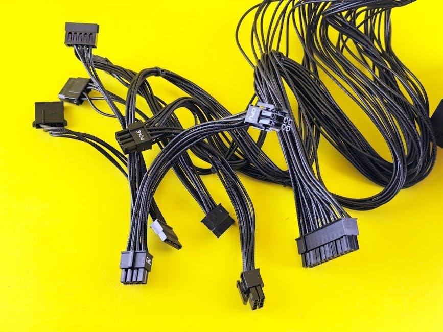
Identifying Key Connectors and Wiring Colors
Accurate identification of connectors and wiring colors is paramount for a successful LS swap. The LS harness utilizes a variety of connectors, each serving a specific purpose. Common connectors include the PCM (Powertrain Control Module) connectors, sensor connectors (MAP, TPS, coolant temperature), fuel injector connectors, and coil pack connectors.
Wiring colors are generally standardized, but variations exist depending on the year and specific engine configuration. For instance, red wires typically indicate power, black wires are ground, and various colors denote specific sensor signals. A detailed wiring diagram specific to your engine and harness is absolutely essential.
Carefully trace each wire from the connector to its origin, noting its color and function. Utilize a multimeter to verify continuity and identify any damaged or broken wires. Proper labeling of each wire during the process will significantly simplify troubleshooting later on. Ignoring this step can lead to frustrating errors and potential engine damage.
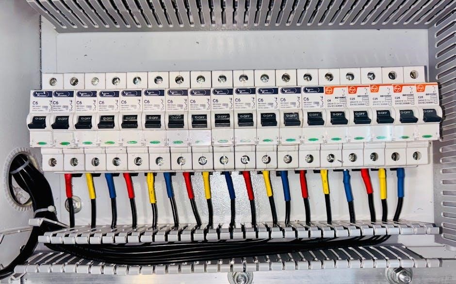
Power and Ground Connections
Establishing solid power and ground connections is the foundational step in LS wiring. The LS engine requires a dedicated 12V power source, typically connected directly to the battery via a high-amp fuse. Multiple ground connections are crucial; connect the harness ground wires to clean, unpainted metal on the engine block and chassis.
Insufficient grounding is a common cause of electrical issues. Use heavy-gauge wiring (10-12 AWG) for both power and ground to minimize voltage drop. Ensure all connections are secure and corrosion-free. A star grounding scheme, where multiple ground wires converge at a central point, is highly recommended.
Double-check polarity before connecting the power wire to prevent damage to the PCM and other electronic components. A reliable power and ground system ensures stable operation and prevents erratic behavior from the engine management system.
Sensor Wiring (MAP, TPS, Coolant Temp, etc.)
Accurate sensor readings are paramount for proper engine operation. The LS engine relies on numerous sensors – Manifold Absolute Pressure (MAP), Throttle Position Sensor (TPS), Coolant Temperature Sensor (CTS), and others – to provide crucial data to the Engine Control Module (ECM). Each sensor has a specific wiring configuration; consult the wiring diagram for your harness.
Pay close attention to the sensor signal wires, power wires, and ground wires. Incorrect wiring can lead to inaccurate readings, causing poor performance or even engine damage. Use a multimeter to verify signal voltages and resistances. Ensure all connections are clean and secure.
Properly identifying and connecting these sensors is vital for optimal fuel delivery, ignition timing, and overall engine management. Double-check each connection against the wiring schematic before proceeding.
Fuel System Wiring (Fuel Pump, Injectors)
The fuel system requires careful wiring to ensure reliable fuel delivery. This involves connecting the fuel pump relay, fuel pump power supply, and injector wiring. The fuel pump relay typically requires a signal from the ECM to activate, providing power to the fuel pump. Verify the correct relay is used and properly grounded.
Injector wiring is critical for precise fuel control. Each injector receives a pulsed signal from the ECM, controlling the amount of fuel injected. Ensure the injector wiring is correctly polarized and that all connections are secure. Incorrect wiring can lead to lean or rich conditions.
Double-check all fuel system wiring for proper voltage and continuity. A faulty connection can cause fuel starvation or overfueling, potentially damaging the engine.
Ignition System Wiring (Coil Packs, Distributorless Ignition)
LS engines utilize a distributorless ignition system, relying on coil packs to generate the spark. Wiring these coil packs correctly is paramount for proper engine operation. Each coil pack requires a constant 12V power supply, a ground connection, and a trigger signal from the ECM. Verify the polarity of the power and ground connections.
The ECM controls the timing and duration of the spark signal sent to each coil pack. Ensure the coil pack wiring is correctly connected to the corresponding ECM outputs. Incorrect wiring can result in misfires or a complete lack of spark.
Carefully inspect all connections for corrosion or damage. A weak connection can cause intermittent spark, leading to poor performance. Use dielectric grease on all connections to prevent corrosion.
Troubleshooting Common Wiring Issues
Wiring problems can cause no power, cranking issues, or check engine lights. Systematic diagnosis—checking power, grounds, and connections—is crucial for resolving these frustrating LS swap challenges.
No Power to the Engine
Diagnosing a complete lack of power during an LS swap requires a methodical approach. First, verify the battery is fully charged and properly connected. Then, meticulously check the main power wire running from the battery to the starter solenoid and the primary power feed to the engine control module (ECM). Ensure these connections are clean, tight, and free from corrosion.
Inspect the fuses – both in the engine bay and within the ECM connector. A blown fuse is a common culprit. Next, confirm the ignition switch is functioning correctly and sending power to the ECM when turned to the ‘on’ position. Utilize a multimeter to trace the power path, identifying any breaks or shorts in the wiring. Don’t overlook the possibility of a faulty relay, particularly the power relay supplying the ECM. Finally, double-check all ground connections; a poor ground can effectively prevent power delivery.
Engine Cranks But Doesn’t Start
If the LS engine cranks but fails to ignite, the issue likely lies within the fuel or ignition systems. Begin by verifying the fuel pump is receiving power and priming correctly. Check the fuel pump relay and fuse. Confirm the injectors are receiving a signal from the ECM; a noid light can be invaluable here. Inspect the crankshaft position sensor (CKP) and camshaft position sensor (CMP) signals – the ECM relies on these for timing.
On the ignition side, ensure the coil packs are receiving power and a trigger signal. A faulty coil pack or a wiring issue to the coils can prevent spark. Verify the ECM is properly communicating with the ignition system. A scan tool can reveal any stored codes related to these systems. Finally, double-check all sensor connections for proper seating and continuity.
Check Engine Light Issues
A lit Check Engine Light (CEL) after an LS swap often indicates wiring or sensor problems. Utilize a scan tool to retrieve Diagnostic Trouble Codes (DTCs). Common codes relate to oxygen sensors, MAF sensor (if used), coolant temperature sensor, or fuel trim issues. Carefully review the code definitions and associated freeze frame data to pinpoint the source.
Inspect the wiring to the affected sensor for damage, loose connections, or incorrect polarity. Verify proper sensor operation by comparing live data readings to expected values. Sometimes, a simple re-scan after verifying connections can clear the code. If codes persist, investigate potential ECM configuration errors or compatibility issues with the chosen harness. Ensure all necessary sensors are connected and functioning correctly.
Advanced Wiring Considerations
LS swaps can be customized with aftermarket gauges or forced induction. LS-DYNA software simulates wiring implications, demanding careful planning for integration and optimal performance.
Integrating with Aftermarket Gauges
Integrating aftermarket gauges into your LS swap requires careful consideration of signal sourcing and wiring. Many gauges need data directly from the engine’s sensors – coolant temperature, oil pressure, wideband O2, and more. Your LS wiring harness provides access points for these signals, but you may need adapters or tap-into connectors to avoid cutting factory wiring.
Digital gauges often utilize a CAN bus connection, simplifying wiring significantly. Analog gauges, however, demand individual wire runs for each parameter. Ensure proper grounding for accurate readings and to prevent electrical noise. Consult the gauge manufacturer’s instructions for specific wiring diagrams and requirements. Properly integrating gauges enhances monitoring and provides crucial insights into your engine’s performance, allowing for informed tuning and proactive maintenance.
Wiring for Forced Induction (Turbo/Supercharger)
Wiring for forced induction, whether turbocharging or supercharging, adds complexity to your LS wiring harness installation. Boost control solenoids, intercooler pump relays, and wideband O2 sensors require dedicated wiring and power sources. A crucial element is wiring the boost controller, often needing a signal wire to the ECU for proper fuel and timing adjustments under boost.
Ensure adequate power supply for the intercooler pump and boost controller, utilizing relays triggered by switched ignition power. Wideband O2 sensors demand specific wiring configurations for accurate air/fuel ratio monitoring. Carefully route wiring away from exhaust heat and moving parts. Proper wiring ensures reliable boost control, optimal engine performance, and safeguards against potential damage from excessive boost pressures.
LS-DYNA Software and Wiring Implications (Simulation)
While seemingly unrelated, LS-DYNA, a finite element analysis software, can indirectly impact LS wiring harness considerations, particularly in high-performance applications. Engineers utilize LS-DYNA to simulate crash scenarios and structural integrity, potentially revealing areas where wiring harness routing needs reinforcement or shielding. This is especially relevant in vehicle builds undergoing rigorous testing or competition.
Understanding potential stress points identified through simulation informs harness design, ensuring wires aren’t susceptible to damage from chassis flex or impact. Furthermore, thermal simulations can highlight areas requiring heat shielding for wiring. Though not directly involved in the wiring process, LS-DYNA’s insights contribute to a more robust and reliable overall system, enhancing safety and performance.
Resources and Support
Online forums and dedicated communities offer invaluable assistance with LS wiring. Pace Performance provides specialized LS harness solutions, alongside professional wiring services for complex builds.
Online Forums and Communities
LS engine swap forums are a treasure trove of information for tackling wiring challenges. These platforms connect enthusiasts who have already navigated the complexities of LS wiring harnesses, offering practical advice and troubleshooting assistance. Members frequently share wiring diagrams, pinout information, and solutions to common issues encountered during installations.
Active communities, like those found on dedicated automotive websites and social media groups, provide a space to ask questions, share progress, and learn from others’ experiences. Searching these forums often reveals detailed threads addressing specific wiring scenarios, including integrating aftermarket components or resolving error codes.
Many users document their entire LS swap journey, including detailed photos and videos of the wiring process, which can be incredibly helpful for visual learners. Don’t hesitate to post your own questions and contribute to the collective knowledge base – the community thrives on shared expertise!
Professional Wiring Services
For those intimidated by the intricacies of LS wiring, or lacking the time and tools, professional wiring services offer a reliable solution. These specialists possess in-depth knowledge of LS engine management systems and can create custom wiring harnesses tailored to your specific application. They eliminate the risk of errors that could lead to costly damage or performance issues.
Pace Performance is frequently cited as a reputable provider of pre-made LS wiring harnesses, simplifying the installation process significantly. Professional services can also handle complex integrations, such as adding forced induction or aftermarket gauges. While more expensive than DIY approaches, the peace of mind and guaranteed functionality can be invaluable.
Consider obtaining quotes from multiple wiring services, detailing your engine specifications and desired features. A well-executed professional wiring job ensures a clean, reliable, and high-performing LS swap.
Pace Performance Harness Solutions
Pace Performance has established itself as a leading provider of LS wiring harness solutions, catering to a wide range of swap applications. They offer both universal and application-specific harnesses, designed to streamline the installation process and minimize wiring complexity. Their harnesses are known for their quality construction and detailed instructions, making them a popular choice among enthusiasts.
Specifically, Pace Performance addresses the common dread of cutting and splicing wires associated with LS swaps. Their pre-wired harnesses significantly reduce installation time and the potential for errors. They provide solutions for various engine families, including LS, LT, and even older small-block Chevrolets.
Exploring their catalog reveals options for different levels of customization and features, ensuring a harness that perfectly matches your project’s needs. Investing in a Pace Performance harness can be a worthwhile step towards a successful and reliable LS swap.